Adaptive Loop Filter

Welcome to our new article about Versatile Video Coding!
VVC, also known as H.266, MPEG-I Part 3, is the new video compression standard developed by the Joint Video Experts Team (JVET), that is a united video expert team of the MPEG working group of ISO/IEC JTC 1, and the VCEG working group of ITU-T.
Today we will consider in more detail one of in-loop filtering coding tools — Adaptive Loop Filter. Before we go any further you can take a quick look at our overview article about filtering in VVC.
Introduction
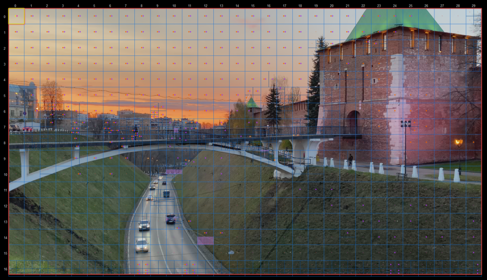
Adaptive Loop Filter (ALF) is one of in-loop filtering techniques from VVC. The main aim of VVC is to improve compression efficiency of the H.265/HEVC standard by 30–50% compression rate for the same perceptual quality.
The filter is adaptive in the sense that the coefficients are signaled in the bitstream and can be designed based on image content and distortion of the reconstructed picture. ALF is applied to reduce distortion introduced by the encoding process and improve the reconstructed quality.
Block classification
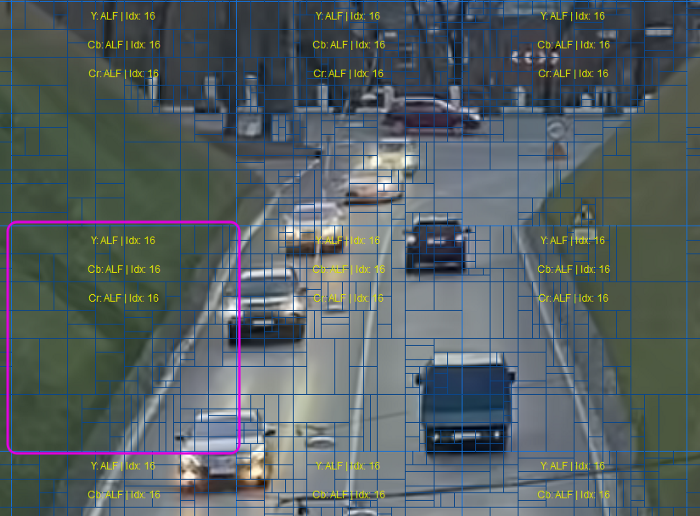
The main idea of ALF is to apply a classification to partition a set of all sample locations into multiple classes. After that, Wiener filters are calculated and applied for each class.
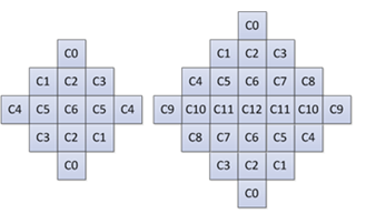
Two diamond filter shapes are used. The 7×7 diamond shape is applied for luma component and the 5×5 diamond shape is applied for chroma components.
For luma components, each 4x4 block is categorized into one out of 25 classes. The classification index is derived based on its directionality and a quantized value of activity, which is computed, involving calculation of gradients in four directions for the reconstructed luma samples.
For chroma components in a picture, no classification method is applied.
Geometric transformations of filter coefficients and clipping values
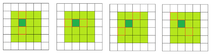
Before filtering each 4×4 luma block, geometric transformations such as rotation or diagonal and vertical flipping are applied to the filter coefficients and to the corresponding filter clipping values depending on gradient values calculated for that block. This is equivalent to applying these transformations to the samples in the filter support region. The idea is to make different blocks to which ALF is applied more similar by aligning their directionality.
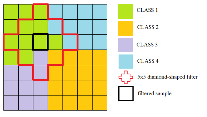
Filtering process
Each sample location is classified into one of four classes and filtered by diamond-shaped filter. All shadowed samples affect the filtering process of the center location.
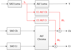
Cross-component ALF
Adaptive Loop Filter comprises luma ALF, chroma ALF and cross-component ALF (CC-ALF). The ALF filtering process is designed so that luma ALF, chroma ALF and CC-ALF can be executed in parallel.
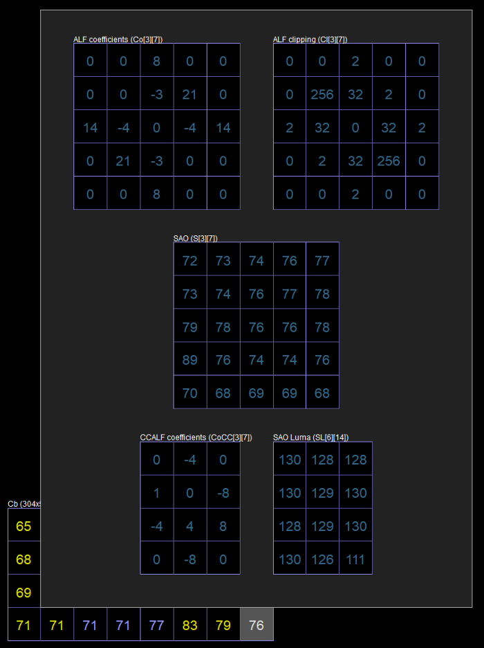
CC-ALF, uses luma sample values to refine each chroma component by applying an adaptive, linear filter to the luma channel and then using the output of this filtering operation for chroma refinement.
CC-ALF filter selection is controlled at CTU-level for each chroma component. The design uses a 3x4 diamond shape with 8 taps.
The picture below provides a system level diagram of the CC-ALF process with respect to the SAO, luma ALF and chroma ALF processes.
Conclusion
We did it! Thanks for reading and see you soon for new articles about filtering!
References
- Algorithm description for Versatile Video Coding and Test Model 11(VTM 11)
- J. Erfurt, Wang-Q Lim, H. Schwarz, D. Marpe, T. Wiegand: Extended multiple feature-based classifications for adaptive loop filtering