VQ Analyzer — Guided Tour. In-loop filtering

Welcome to our new VQ Analyzer (Video Codec Analyzer) Guided Tour!
Before we start, a few words about the VQ Analyzer itself.
The VQ Analyzer is a graphical coded video bitstream analysis tool, supporting the following coding standards:
- VVC, SHA-1 (VTM 10.0 tag): 45dfe06835aea43f37456ea54972ef31b765eacf
- AV1, SHA-1 (av1-normative branch of AOM source): acc3f97753f67e0ce7290b98b7bb71152fe5e264
- HEVC: (ISO/IEC 23008–2 MPEG-H Part 2 or ITU-T H.265) , 8/10-bit
- HEVC: RExt extension, 8/10/12-bit, 4:0:0/4:2:0/4:2:2/4:4:4
- HEVC: SCC extension, conform to HM + SCM 8.5 in reference code
- HEVC Scalable/Multiview Extension
- Google’s VP9, profiles 0,1,2,3, 4:2:0/4:2:2/4:4:0/4:4:4, 8/10/12-bit
- AVC: (H.264/AVC, ISO/IEC 14496–10, MPEG-4 Part 10), except SVC/MVC
- MPEG2 (ISO/IEC 13818–2 Part 2), 4:2:0/4:2:2, 8-bit
- MKV container
- MP4 container
- MPEG2 TS/PS container
- AVI container
- Mpeg Media Transport container.
Once a bitstream is loaded, the tool allows the user to inspect each major step of the decoding process visually and numerically, and the structure of the coded image can be explored. This data can be used as a visual reference when learning about HEVC/VP9/AVC/MPEG2/AV1/VVC or when debugging a particular encoder or decoder.
Introduction
VVC (Versatile Video Coding), also known as H.266, MPEG-I Part 3, is the new video compression standard developed by the Joint Video Experts Team (JVET), that is a united video expert team of the MPEG working group of ISO/IEC JTC 1, and the VCEG working group of ITU-T. The main aim of the VVC is to improve compression efficiency of the H.265/HEVC standard by 30–50% compression rate for the same perceptual quality.
VVC contains many coding tools which reduce distortion between the original and decoded frames produced by lossy coding. Deblocking filter, Sample Adaptive Offset (SAO), Adaptive Loop Filter (ALF) for in-loop filtering are introduced for the VVC standard. Besides that, in VVC, a coding tool called the luma mapping with chroma scaling (LMCS) is added as a new processing block before the loop filters.
These filtering techniques are implemented to reduce distortion introduced by the encoding process.
Deblocking
A deblocking filter is a video filter applied to a decoded compressed video to improve visual quality and prediction performance by smoothing the sharp edges which can form between macroblocks when block coding techniques are used. The filter aims to reduce blocking artifacts and improve the appearance of decoded pictures.
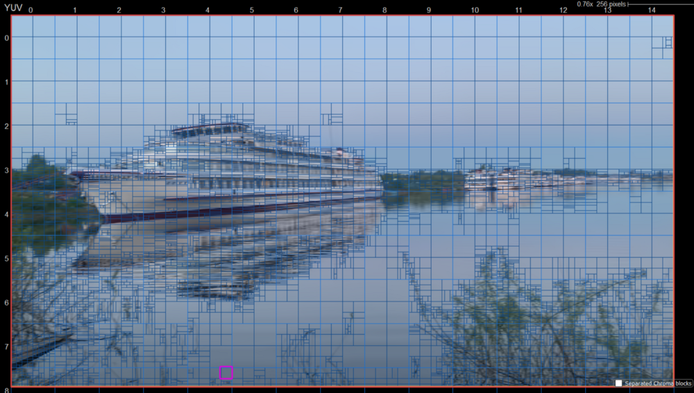
Deblocking filter is applied to the whole picture first.
The filter makes the need on/off decision for Luma/Chroma and produce level of filtering (weak/strong), and finally makes filtering operations.
Loop Filter Mode
Let’s check the deblocking filter decisions in our VQ Analyzer.
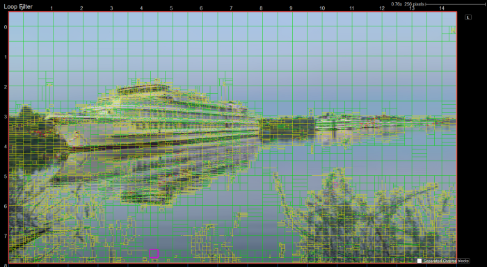
Click “Mode” and choose “Loop Filter” or just press F6.
Loop Filter mode shows all edges processed by the deblocking filter. Edges shown are for the luma deblocking process and are color coded in the following manner:
- Green: Strong luma filter applied
- Yellow: Weak luma filter applied
- Red: No filter applied (but edge was evaluated)
Loop Filter Detail Mode
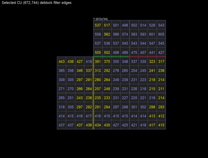
The deblocked sample values can be inspected directly in detail mode. Sample values are indicated in yellow if they were modified by the deblocking process. Filtered edges belonging to the selected CU are shown in thick dashed lines, color coded the same way as in the non-detail mode. Each edge can be selected and clicked, bringing up a window showing the input values to the edge filter. Additionally, the boundary strength is displayed. Edges that were processed but ultimately not filtered (red colored) will indicate the reason.
SAO
Sample Adaptive Offset (SAO) is the process of adding offset to Deblocked pixel values according to SAO type — i.e., based on edge direction/shape (Edge Offset aka EO) and pixel level (Band Offset aka BO) or unchanged (OFF).
Deblocking filter is applied to the reconstructed picture first. SAO filter is then applied to the whole picture which is fully filtered by deblocking filter.
Edge offset
There are four offsets corresponding to four edge shapes (i.e., categories/edge index) for the selected direction. The edge index is referred to as SAO-subtype for EO.
Offset value is added to each deblocked pixel value if it belongs to a given EO type and category, otherwise it is not altered.
Band offset
The whole pixel range (0–255 for 8 bpp) is equally divided into 32 bands as shown in the figure below.
Offset value is added to each deblocked pixel value if it belongs to the range covered by one of the four bands, otherwise pixel value is not altered.
SAO Mode
Click “Modes” -> “SAO” of press F7 to open SAO mode in VQ Analyzer.
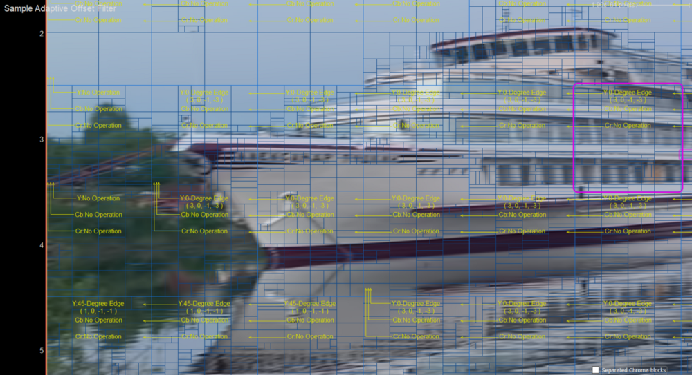
In SAO mode the SAO filter parameters are shown. The mode, and the associated four offsets for each component, are indicated with yellow text, and the merge_up / merge_left flags are indicated with an arrow.
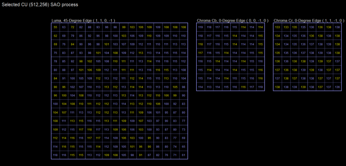
SAO Detail Mode
Entering detail mode on a selected CU will show all samples after being processed by the SAO filter. Sample values that were actually modified by the SAO operation are highlighted in yellow. Each sample can be clicked, bringing up a 3x3 window that shows the input values to the filter process. In the screenshot below, the 45-degree edge filter inputs are the samples to the lower left and upper right. Samples that cannot be modified by the filter are indicated in red.
ALF
Adaptive Loop Filter (ALF) reduces the blocking artifacts carried out at encoding schemes.
The filter minimizes the mean squared error between the original picture and the output picture of SAO. The filter is adaptive in the sense that the coefficients are signaled in the bitstream and can be designed based on image content and distortion of the reconstructed picture.
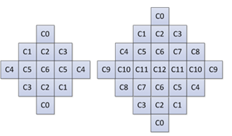
Subsequently, block-based adaptive loop filtering was proposed where the ALF could be enabled and disabled on a block (i.e. coding unit) basis. The encoder would signal to the decoder the map of blocks of deblocked picture on which to apply ALF to improve the reconstructed quality. The 7×7 diamond shape is applied for luma component and the 5×5 diamond shape is applied for chroma components.
At the decoder, a laplacian-based local activity is used to switch between the different filters on a block-by-block basis.
A new feature in VVC, CC-ALF, uses luma sample values to refine each chroma component by applying an adaptive, linear filter to the luma channel and then using the output of this filtering operation for chroma refinement.
Picture below provides a system level diagram of the CC-ALF process with respect to the SAO, luma ALF and chroma ALF processes.
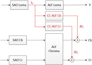
In the VVC, CC-ALF filter coefficients are computed by minimizing the mean square error of each chroma channels with respect to the original chroma content.
Adaptive Filter Mode
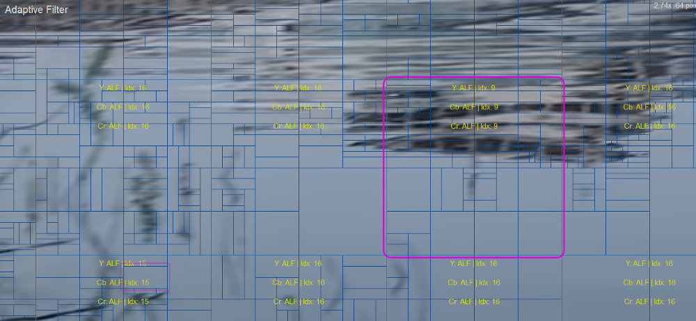
Let’s look at ALF mode in VQ Analyze. To do this, click “Modes”->”Adaptive Filter” or just press F8.
Adaptive Filter mode shows the following ALF parameters:
- On/Off ALF on coding units
- Filter Idx for Luma and Chroma components
- Blocks where ALF for cross components (CC ALF) is applied
LMCS
In VVC, a new process called the luma mapping with chroma scaling was added (this process was previously known as the adaptive in-loop reshaper). This new process is performed before deblocking.
The reference algorithm in VTM10 is designed differently for SDR, HDR PQ and HDR HLG sequences. For SDR and HDR HLG sequences, the encoder algorithm is based on local luma variance and optimized for PSNR metrics. For HDR PQ sequences, the encoder algorithm is based on luma values and optimized for wPSNR (weighted PSNR) metrics.
LMCS has two main components:
- in-loop mapping of the luma component based on adaptive piecewise linear models
- for the chroma components, luma-dependent chroma residual scaling is applied
The in-loop mapping of the luma component adjusts the dynamic range of the input signal by redistributing the codewords across the dynamic range to improve compression efficiency.
Chroma residual scaling CS is used to compensate for the interaction between brightness and chroma of the corresponding position.
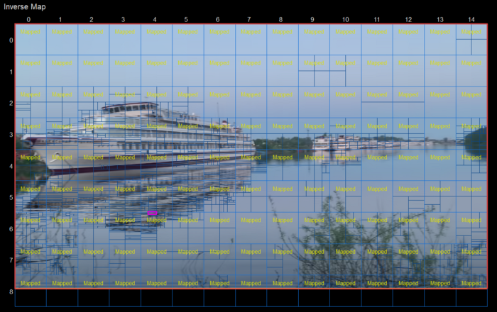
Inverse Map Mode
To see LMCS info in VQ Analyzer click to “Modes” -> “Inverse Map” or press F5.
Conclusion
So, In-loop filtering is an important part of VVC. Using filters in the decoding loop increases the quality of the reference pictures and hence the compression efficiency. VQ Analyzer gives you full-frame visualization features to accelerate development by providing insights on the algorithm choices that produce a bitstream.
Thanks for reading and see you again in next VQ Analyzer Guided Tours!
References
- Algorithm description for Versatile Video Coding and Test Model 10(VTM 10)
- Understanding in-loop filtering in the HEVC video standard
- Adaptive Trilateral Filter for Hevc
- Luma Mapping with Chroma Scaling in Versatile Video Coding (VVC)