Non-rectangular block splitting in AVS3: AWP and SAWP modes
In this paper, we will review the non-rectangular block splitting method for prediction in the currently developing codec Audio Video Standard (AVS3 phase 2): Angular Weighted Prediction (AWP) and Spatial Angular Weighted Prediction Mode (SAWP).
Why non-rectangular?
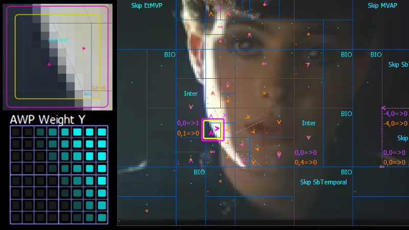
One of the most fundamental techniques in video coding is partitioning a picture into smaller blocks for prediction and transform coding. Different tree-structured methods were developed to split variable block sizes during codec evolution. Although the partitioning structure becomes more flexible and efficient, the rectangular shape of blocks is not always the best way to describe an arbitrary object shape (pic 1).
Usually, when the object boundary is not horizontal or vertical, more blocks are required to split areas by a slope line. Therefore, non-rectangular block splitting techniques were developed to handle such cases.
Overview of comparable tools
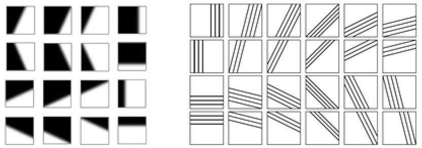
Compound wedge prediction (CWP) was adopted in AV1; it is based on using predefined weight masks; there are 16 variants for each block size [2]. Geometric partition mode (GPM) was adopted in VVC [4]; it supports 64 partition variants (pic 2). All these masks are being used in the same way to divide block into two parts by a slope line. For a camera-captured content, sample values near the object's edges usually have a smooth transition; therefore, masks are designed with a non-binary transition area.
AWP
AVS3 developed Angular Weighted Prediction mode (AWP) to handle non-rectangular prediction; it supports 8 angle and 7 offset values (56 combinations) for one block size, and it also supports two variants of the transition area smoothness. It seems to be a compromise: more flexible than CWP in AV1 and less computational complexity than GPM in VVC.
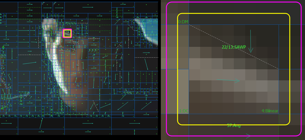
SAWP
An interesting remark is that both AV1 and VVC use the described methods as Inter Bi-prediction technique, but AVS3 has also applied the splitting method for Intra prediction; it is called SAWP - Spatial Angular Weighted Prediction. So, for AVS3, we have AWP - for Inter prediction and SAWP – for Intra prediction.
AWP & SAWP Algorithm stages
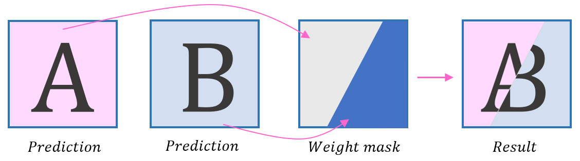
The decoding algorithm is based on three parts:
- Derive independent predictions for part A and part B
- Derive AWP weight mask
- Derive prediction results by combining parts using the weight mask
Prediction parts derivation
For SAWP mode, parts are predicted using intra angular prediction; for AWP mode, motion-compensated prediction is used.
Weight mask derivation
Weight mask is filled in a way similar to the angular intra prediction – a block is generated using the reference line and angle.
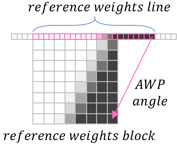
Calculation of mask is followed by three steps:
- Derive the length of reference weight line
- Fill reference weight line
- Fill reference weight block based on the line
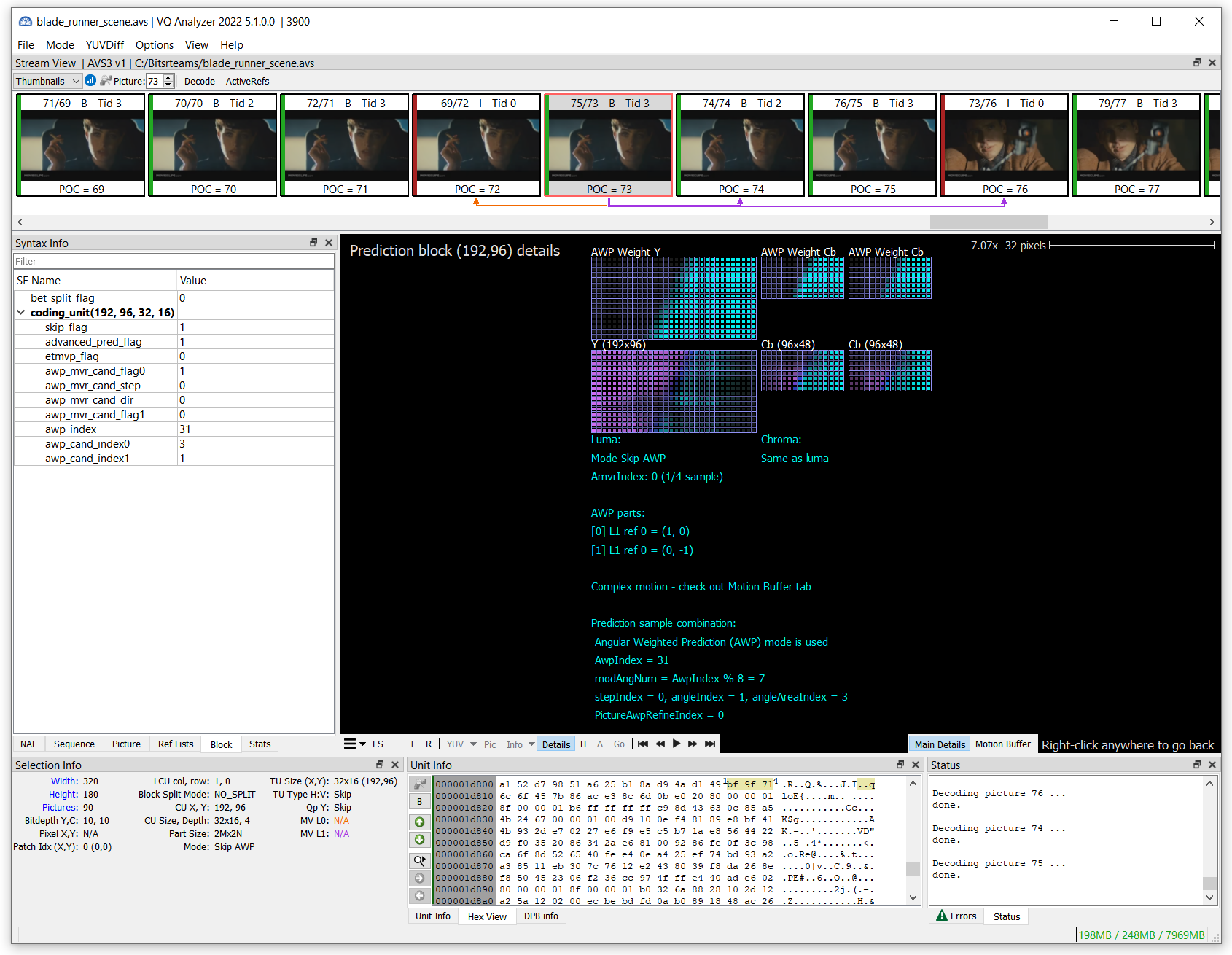
Weight Mask signaling
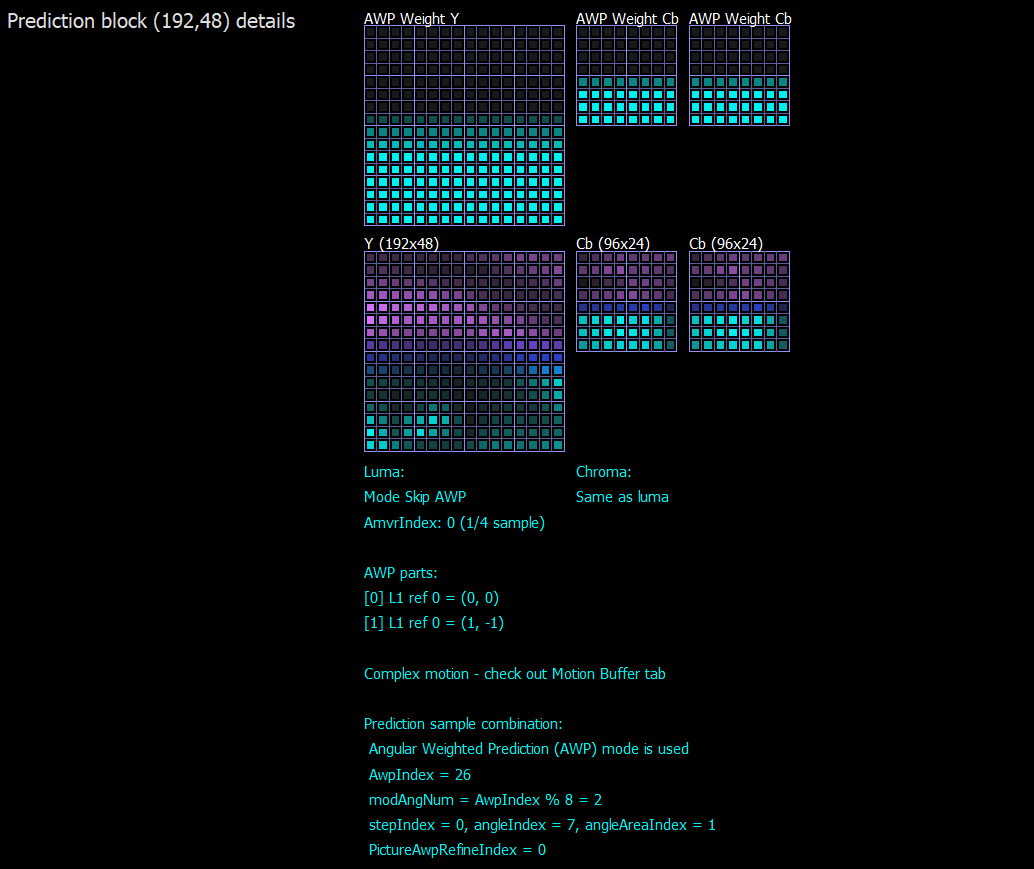
Mask form is derived by AwpIndex that is signaled in the bitstream. For B picture value, it is in the range of 0..55 for 56 combinations and used directly; for P picture value, it is derived by predefined tables for different CU sizes.
Mask boundary smoothness is derived from the binary value PictureAwpRefineIndex signaled in the bitstream.
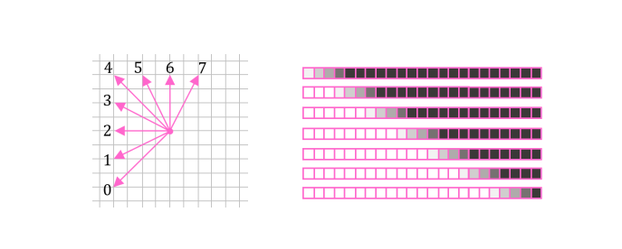
There are 8 possible angles and 7 steps for generating the initial reference line (pic 6). Angles are grouped in AwpIndex by sets for each step.
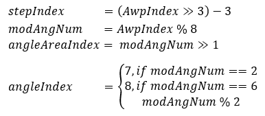
AwpIndex is translated to the following parameters for further calculations:
Calculations
Determine vL, length of the valid initial reference weights line.
Half pixel precision is used for the initial line.
For the first 4 angles, the column on the left is taken as the reference line.
For the last 4 angles, the row on the top is taken as the reference line (pic 6):
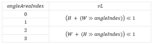
where H and W are the current block’s height and width.
Fill initial reference weight line Lw with the length vL (pic 5).
Pattern for selected angle and step could be derived from the next equation:
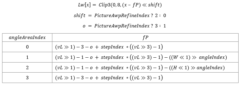
Where PictureAwpRefineIndex sets the transition area smoothness.
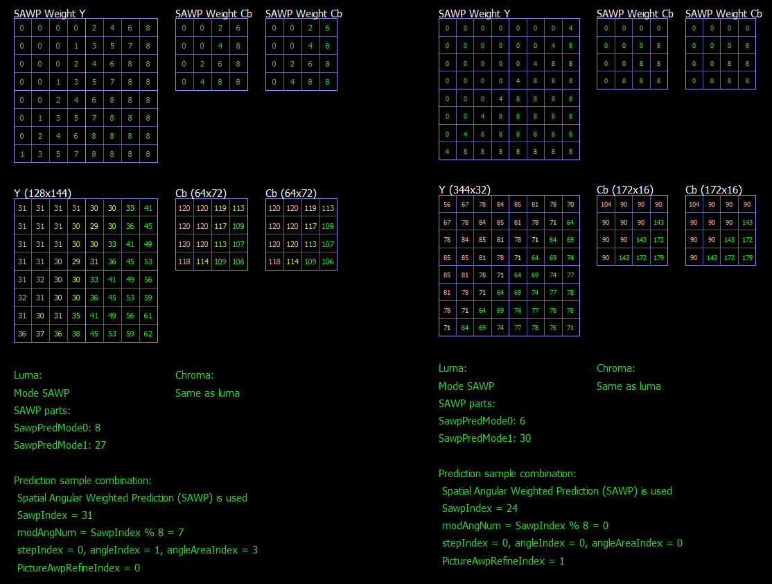
Fill the luma weight mask using the reference line.
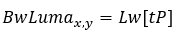
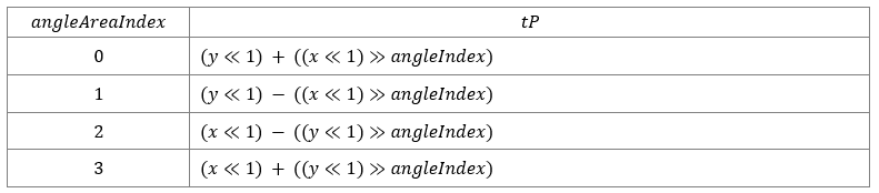
Where tP is derived from the following tables.
For AWP mode in B picture or SAWP mode:
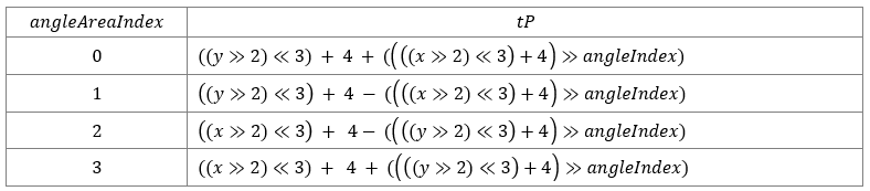
For AWP mode in P picture:
Fill the chroma weight mask with the luma weight mask.
For AWP mode in B picture or SAWP mode:

For AWP mode in P picture:

Combine the final prediction result
Use prediction parts A and B and weight maps for luma and chroma, respectively:

References:
- AVS3 - Part 2: Video. Draft text of AVS video group
- Y. Sun, F. Chen, L. Wang and S. Pu, "Angular Weighted Prediction for Next-Generation Video Coding Standard," 2021 IEEE International Conference on Multimedia and Expo (ICME), 2021, pp. 1-6, doi: 10.1109/ICME51207.2021.9428315
- X. Xu and S. Liu, "Overview of Screen Content Coding in Recently Developed Video Coding Standards," in IEEE Transactions on Circuits and Systems for Video Technology, vol. 32, no. 2, pp. 839-852, Feb. 2022, doi: 10.1109/TCSVT.2021.3064210.
- Algorithm description for Versatile Video Coding and Test Model 12 (VTM 12)