Bi-directional Optical Flow (BDOF) Prediction Refinement in VVC

Bi-directional Optical Flow (BDOF) Prediction Refinement in VVC
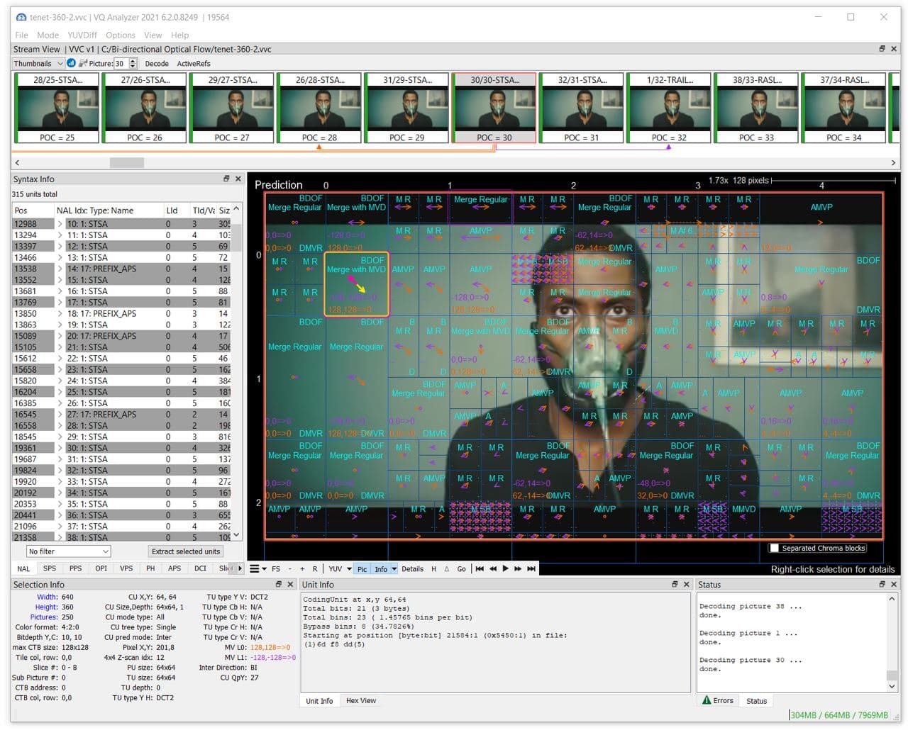
Welcome to the new article about Versatile Video Coding! Today we'll delve into a new VVC coding tool – Bi-directional Optical Flow. For demonstration, we will use VQ Analyzer — a bitstream analysis tool developed by ViCueSoft.
Target
BDOF is used to pixel-wise compensate the fine motion missed by the block-based motion compensation [1]. It reduces prediction error without additional signaling - refinement derivation is performed on the decoder side, just like in DMVR. However, calculations are less complex compared to DMVR because there is no search for motion. The refinement is derived by explicit formulas.
General bi-prediction in VVC is an averaged combination of two prediction blocks from references L0 and L1:

Due to the limitation of block-based motion compensation, the motion is not ideal for the whole block, and usually, there remain displacements between the samples inside two prediction blocks. BDOF target is compensation of such fine displacements of prediction samples for each pixel.
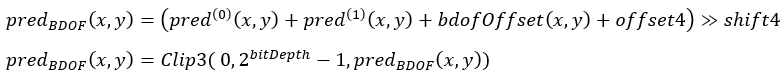
Here is the final BDOF formula, and it will be described below:

Concept
BDOF (BIO) concept was studied during HEVC development, and in VVC, simplified and improved several times [4]: early termination strategy, internal bit depth decrease, low complexity gradient calculation, and motion refinement.
The main idea is to use differential optical flow equation to derive motion vector refinement in bi-predicted blocks. That becomes possible with a set of safe assumptions:
- Objects are moving with constant speed; therefore, the so-called "steady motion" model can be employed
- Objects’ luminance does not change, so optical flow partial differential equation (PDE) is valid
- Only fine motion is lost using the standard block-based prediction
- For simplicity reasons, the remaining motions are assumed to be symmetric and equal in value (BDOF is applied only for equal L0 and L1 POC distances)
The optical flow differential equation can be expressed as follows
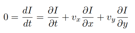
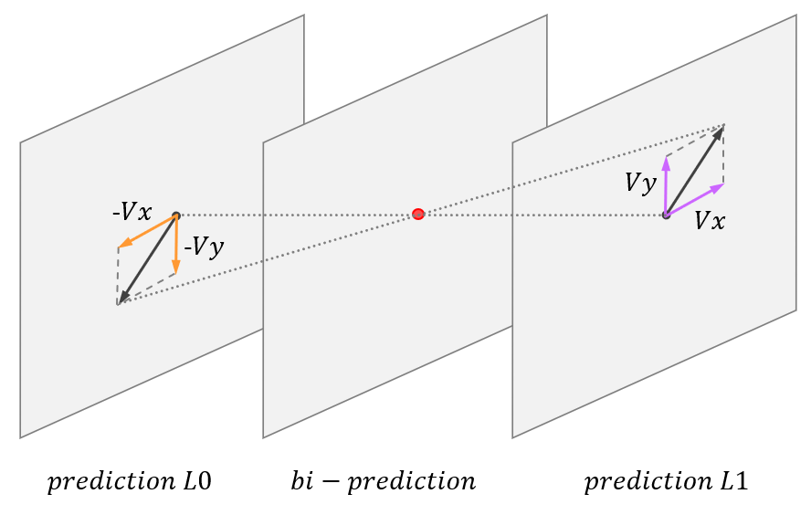
where I is luminance, motion (Vx, Vy) describes the remaining minor displacement (Figure 1) and can be used to compensate prediction.
Calculations
A motion refinement (Vx, Vy) is calculated by minimizing the difference between the L0 and L1 prediction samples. In the VVC BDOF version, this is solved in the following way.
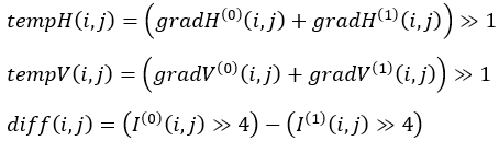
1. Calculate horizontal and vertical gradients for L0 and L1 predictions (K = 0,1)
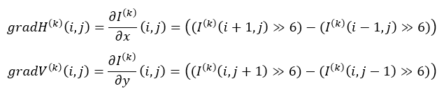
where I(k)(i,j) are the sample values at coordinates (i,j) of the prediction signal in list K
2. Calculate cross- and autocorrelations for gradients: sGx2, sGy2, sGxdI, sGydI and sGxGy
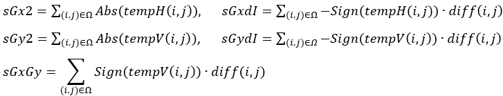
where Ω is a 6×6 window around the 4×4 subblock (Figure 5)
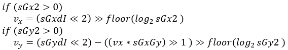
3. Calculate motion refinement (Vx, Vy). It is set (0,0) by default and then derived using the cross- and auto-correlation terms using the following:
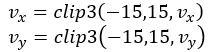
Values are clipped after:
4. After motion refinement (Vx, Vy) is derived, it is applied to calculate luma refinement

5. Refinement is finally used in luma prediction:
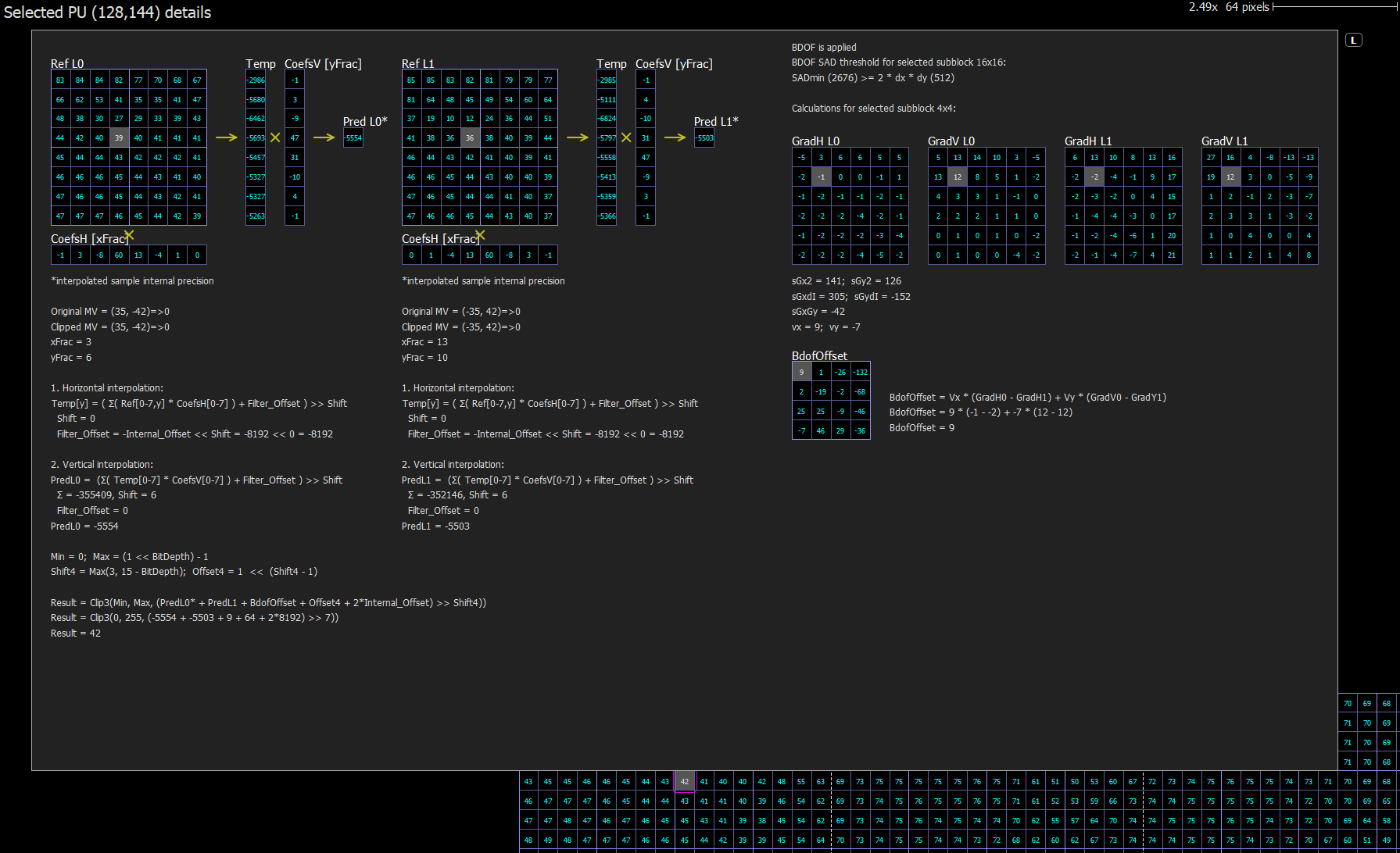
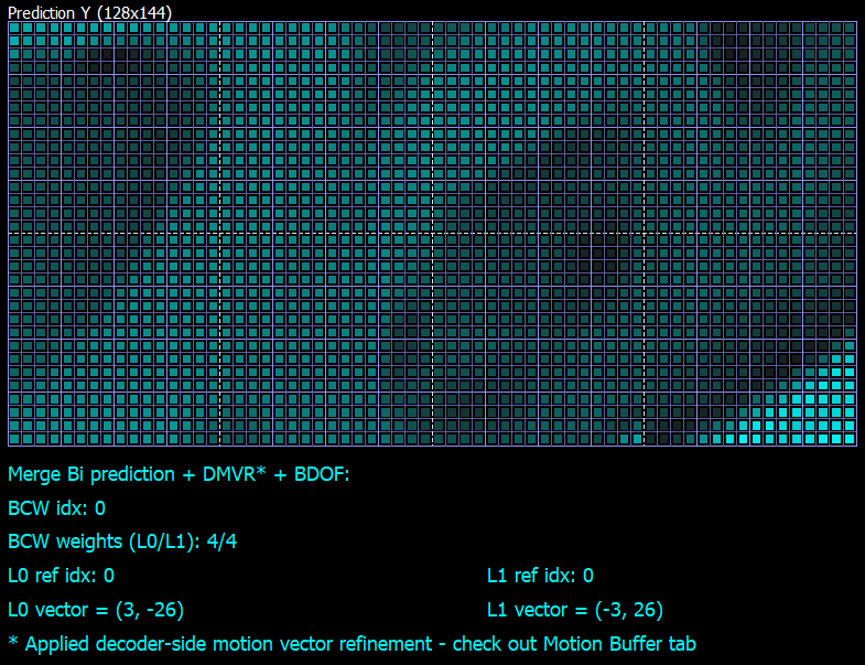
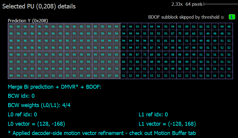
Let's look at how BDOF refinement could be demonstrated with VQ Analyzer:
Algorithm details
16x16 subblock processing
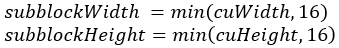
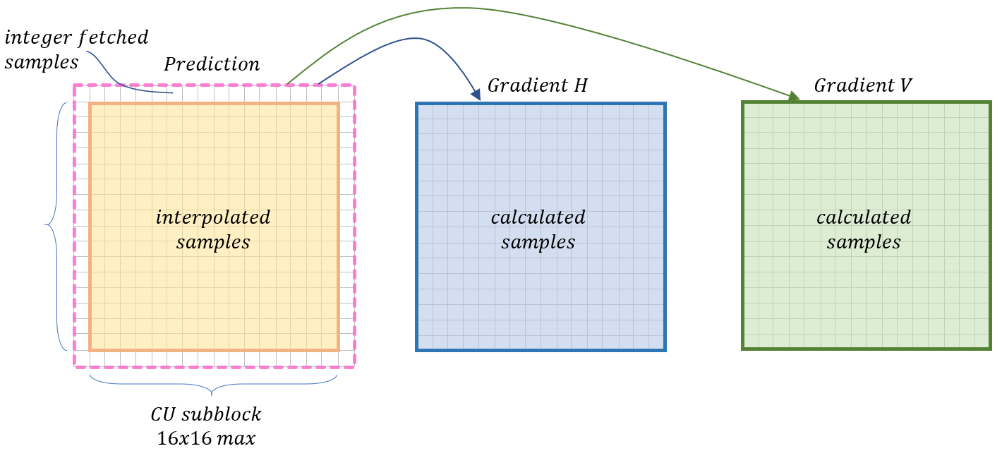
Max unit size for BDOF processing is 16x16. So when the width or height of a CU is larger than 16 luma samples, it will be split into subblocks 16x16 max (Figure 3). 16x16 Subblock boundaries are treated as the CU boundaries in the BDOF process.
This is done to reduce internal buffer size for implementations, align BDOF unit size with DMVR processing, and allow early termination by SAD calculated in DMVR.
To control the complexity of generating out-of-boundary prediction samples (white area on Figure 4) while calculating gradients, they are generated without interpolation – simply copied from the nearest integer sample positions in the reference picture [6]. Inner predictions samples (orange area) are generated as usual with 8-tap interpolation filter.
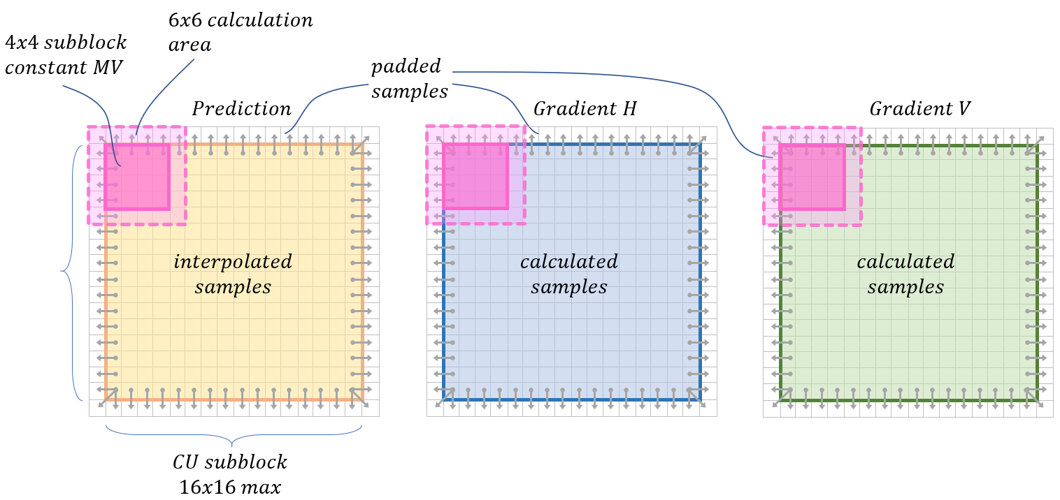
For the subsequent calculations in the BDOF process, when any sample and gradient values outside the CU boundaries are needed, they are copied from their nearest neighbors (figure 5).
4x4 constant MV subblocks
To reduce the computational complexity of the derivation of remaining local motions, each 4×4 subblock (Figure 5) uses the same vector (Vx, Vy), so it’s calculated once for the whole subblock [8].
6x6 calculation area
The vector (Vx, Vy) for each 4×4 subblock is calculated from the extended 6×6 area (noted as Ω above) to make the derived motion field more stable. The area is extended by adding one row/column to each side, so the original 4x4 subblock is located in the center (Figure 5).
Early termination
For each processing subblock (up to 16x16), the BDOF process could be skipped [5]. The condition used is SAD calculated for subblock in DMVR mode to avoid additional complexity. So, the skip is possible when BDOF is combined with DMVR mode (Figure 6).

When SAD is lower than the threshold, it is assumed that prediction quality is good, and the BDOF process is skipped.
Features
- Applied to luma only
- Could be combined with DMVR
- Processing is done by 16x16 subblocks
Restrictions
- CU is "true" bi-prediction mode – one reference is in the future, and another is in the past
- The distances (POC difference) from two reference pictures to the current picture are the same
- Both reference pictures are short-term reference pictures
- CU has more than 128 luma samples
- CU height and CU width >= 8 luma samples
- CIIP mode is not used for the current CU
- Can’t combine with Affine, MVD, BCW, WP, SbTMVP, CIIP modes
References
[1] A. Alshin and E. Alshina, “Bi-directional optical flow,” Joint Collaborative Team on Video Coding (JCT-VC), doc. JCTVC-C204, Oct. 2010.
[2] A. Alshin, E. Alshina, and T. Lee, “Bi-directional optical flow for improving motion compensation,” in 2010 Picture Coding Symposium, Dec. 2010, pp. 422–425.
[3] A. Alshin and E. Alshina, “Bi-directional optical flow for future video codec,” in 2016 Data Compression Conference, Mar. 2016, pp. 84–90
[4] H. Yang et al., "Subblock-Based Motion Derivation and Inter Prediction Refinement in the Versatile Video Coding Standard," in IEEE Transactions on Circuits and Systems for Video Technology, vol. 31, no. 10, pp. 3862-3877, Oct. 2021, doi: 10.1109/TCSVT.2021.3100744.
[5] X. Xiu, Y. He, Y. Ye, C.-Y. Chen, C.-Y. Lai, Y.-W. Huang, and S.-M. Lei, “CE9-related: A simplified bi-directional optical flow (BIO) design based on the combination of CE9.5.2 and CE9.5.3,” Joint Video Experts Team (JVET), doc. JVET-K0485, Jul. 2018.
[6] X. Xiu, Y. He, and Y. Ye, “CE9-related: Complexity reduction and bitwidth control for bi-directional optical flow (BIO),” Joint Video Experts Team (JVET), doc. JVET-L0256, Jul. 2018.
[7] Y. Kato, T. Toma, and K. Abe, “Simplification of BDOF,” Joint Video Experts Team (JVET), doc. JVET-O0304, Jun. 2019.
[8] H.-C. Chuang et al., “EE-related: A block-based design for bi-directional optical flow (BIO),” Joint Video Experts Team (JVET), doc. JVETF0022, Mar. 2017.
[9] Chen, J.; Ye, Y.; Kim, S. “Algorithm description for Versatile Video Coding and Test Model 11 (VTM 11)”, Document: JVET-T2002-v2, Jul. 2021
[10] B. Bross, J. Chen, S. Liu, Y.-K. Wang “Versatile Video Coding Editorial Refinements on Draft 10”, Document: JVET-T2001-v2, Sep. 2021